Quantcast
Channel: Yifan Lu
Viewing all 77 articles
Browse latest View live

Analyzing Kindle 4.0

$
0
0

Well, Amazon might as well have stolen my wallet, because I am going to lose a couple hundreds of dollars. However, what fun is a Kindle if we can’t run our own code? (Answer: still pretty fun, but that’s besides the point.) Anyways, I haven’t gotten my hands on the new Kindles yet, but I got the next best thing: a software update from Amazon (http://www.amazon.com/gp/help/customer/display.html/?nodeId=200774090)

If you want to follow me and others try to crack this thing, visit this thread on MobileRead.

I’ll post some of the more important stuff we find on this post, so check back regularly.

  • The update format has changed! No more signatures for each file in the update, the update itself is signed and will refuse to extract unless the signature check passes. That means no more easy way out. To get “kindle_update_tool.py” to recognize and extract the new update, remove the signature (first 0×140 bytes) and change “FC04″ to “FC02″ (Bytes 0×0 to 0×4 after trimming the signature header). Now delete 4 bytes starting from 0×8 and 6 bytes starting from 0×10. (Offsets depend on the SP01 part removed). Now “kindle_update_tool.py” will recognize it.
  • Kindle 4.0 is codenamed “Yoshi” following “Luigi” (3.0) and “Mario” (2.0) (I can’t remember 1.0). It is built for the iMX50 (800MHz ARM Cortex A8) platform. The Kindle 3 is iMX35 (532MHz ARM) and the Kindle 2/DX is iMX3 (400MHz ARM).

Reversing the Xperia Play emulator (part deux)

$
0
0

The last time we spoke, I managed to run any PSX game on the Xperia Play by redirecting some function calls. Well, since then Sony (you could say) fixed it (still don’t know how, I should look into it one day, I’m guessing they revoked the certificates for Crash Bandicoot) and people running Android 2.3.4 on the Xperia Play can’t use PSXPeria anymore. I’ve re-patched it a while ago, but never got the chance to modify the patching tool to use the new method (I really hate Java and don’t want to use it, so I held back.) until today. As customary to my releases, I will begin by telling more than what you want to know about how it works.

Previously on “cracking the emulator”…

If you haven’t read the last posts I’ve made about how I reverse engineered the emulator data format and binary, you may want to, but I’ll summarize it in a few words. Basically, the emulator was separated into two binaries bin-one decrypts bin-two and bin-two asks bin-one to decrypt and load the game’s table-of-contents which is used to load the game. The TOC is important because anyone can replace the game data files, but it won’t load because the TOC contains addresses of the places to decompress in the game data. Well, after the hard part of reversing the formats and finding all this out, the actual patch was fairly easy. All we did was make a new library with the same function name as the one that is used by bin-two to query bin-one for the TOC, and use it to load the TOC for our custom game and make sure that library loads before Sony’s and the rest is almost magic. We don’t need to overwrite any function pointers or even touch the emulator because the linker looks for the first definition of a function and calls it.

How Sony made our lives harder

So version 1 is always easiest to break. This applies for almost everything. The PSP, the iPhone, the DS, etc. Version 2 is where it gets real. So what are the changes? First of all, no more bi-binary system. There is a single binary that does both the decrypting and emulating. Oh, and they removed the symbols so we can no longer search for “GetImageToc” and find where the function is. Also, they’ve started verifying that ISOs.

Finding the needle

Before we can begin to think about patching, we first need to find what to patch. As I’ve mentioned, Sony removed the symbols, so we no longer know what the function names are. We CAN try to map out the entire binary (10MB) and look for something that does what appears to be decrypting a TOC, but we don’t have months or a team of assembly experts. What we DO have is the older version of the binary that has the symbols. Assuming that they didn’t rewrite the emulator from scratch, the structure should be similar. We open up the old binary, find the function that calls the ones we want to patch, and look for identifying characteristics. What are they? Well, we look for mentions of unique strings and unique calls to standard functions (unique as in something like atoi, not malloc, which is called every other line). Luckily we have both. It seems like a few lines before the function we are interested in, the program does something with the string ”/data/image.ps” and sometimes afterwards, uncompress is called. Now we have the address of the functions we want to patch.

Patching the function

Well, here’s our second problem. What do we patch the function with? We are only limited to the length of what the function originally is, but I’m sure that’s not a problem for experts. I’m not an expert though, so how about we steal what Sony did in version 1? We use dlsym to call the function from a loaded binary in memory. After a quick trip to an assembly reference, I wrote the following code: https://github.com/yifanlu/PSXPeria-Wrapper/blob/master/jni/java-activity-patch.S, I would go into more details, but I believe my comments on the code explains it better than I could. The only other thing we need is to manually define the address for “dlsym” and the offset for the name of the function. ARM assembly uses relative address, so I haven’t come up with a quick way to do this yet. For now, I’m using a calculator and a piece of paper to find the address of dlsym relative to the patch in the program. Comment if you have a better way.

Phase 2

When the game didn’t boot and was frozen on screen, I knew it had to be another obstacle. Our code had to have worked because otherwise, it would have crashed. Debugging with GDB, it seems like the program is blocking forever, seemingly on purpose. To double check, I loaded Crash Bandicoot again, but with my patched emulator and it worked. So, I guess there was a check somewhere that only loads Crash Bandicoot. Yes, I could go back into IDA and look for where the check is and NOP it out, but I was tired by then and my short attention span wants me to work on something else, so I took the easy way out and patched the PSX image with the titleid for Crash Bandicoot. As far as I know, this shouldn’t affect anything in terms of compatibility, but farther tests are needed.

Next week on “cracking the emulator”…

Version 3 of the emulator is already out and is distributed in the PS-Suite games in the Japanese PSN store (on the Play). I already took a look at it, and the emulator did not seem to be updated, so I didn’t try hard to patch it. However, it seems that they implemented many new security mechanisms in the PS-Suite PSX games. For starters, there is a public-private key exchange to make sure all the files in the APK are untouched, and I’m pretty sure the PS-Image is now encrypted or the format has changed. Now, Sony did not do all this to prevent us from loading our own games (or maybe they did). I suspect it’s to prevent pirates from stealing the PSN games. Which means that if I crack the version 3 emulator, I may be helping piracy. This means, I will most likely not touch the PS-Suite emulators, and if I do, two things have to happen. 1) I need to be sure that the emulator has much better compatibility, and 2) I need a way to make sure that my tool isn’t going to be used for piracy. So I guess this may be the last release for a while.

Links

Project Page
Source
Downloads

Kindle Touch (5.0) Jailbreak/Root and SSH

$
0
0

Update Kindle 5.0.3 has fixed the hole to allow for jailbreak. Upgrading an already jailbroken Kindle Touch is fine as the update does not remove the custom key to allow custom packages. If you on 5.0.3 and have not already installed the key, there is a new jailbreak.

So long story short, we can run custom code on the Kindle Touch now but because the operating system has changed so much from Kindle 3, most Kindle modifications will not run without changes. I hope developers will jump to this device now that it’s unlocked. See the bottom of the post for download links. The directions for using are in the readme. Keep reading for technical details on how this came about.

Obtaining the root image
Before we can look for vulnerabilities in the system that would allow us to break in, we need to break into the system and obtain the files that might contain vulnerabilities. Yes, this is a chicken-and-egg problem, but fortunately Amazon is nice enough to help us with this. On every Kindle device is a TTL serial port. I found this port on the bottom of the device when the cover is opened. Fortunately, I did not even have to mess with it, as hondamarlboro and ramirami both managed to get the dump before me. Once we have the root image, it was only a matter of painstakingly looking through all the files to see possible injection vectors.

Looking for the needle

At first, I was digging deep into the system, disassembling and maping out various native libraries, looking for stack overflows (I found a couple but none could be accessed efficiently). I found the bootloader was unlocked but it would be a pain and danger for users (and even developers) to flash custom kernels and such. I also found that the Java code (the Kindle’s entire GUI is written in Java) is NOT obfuscated (which means it would be easier to reverse and later modify) and Amazon has left in many places to place plugins. For example, once someone has the time to figure things out, it would be very possible to write a EPUB extension to read EPUBs from the native reader. There are some other hidden secrets in the device too. The Kindle Touch has an accelerometer and proximity sensor (and a mic, but we know that) but they aren’t used in the software (yet). The more I looked into the system, I was aware that because it was such a huge rewrite, I had misjudged when I assumed that it would be harder to break as Amazon had years to fix the holes now. In fact, I would say that the Kindle 4 is more secure until I found out that Amazon left in SSH in diagnostics mode. Anyways, as I searched up the complexity chain from the bootloader to the kernel to the libraries to the Java interface, I found something very curious. Much of the operating system is no longer written in Java, but are now in HTML5 and Javascript. In fact, many of the interfaces on the Touch are actually web pages in disguise. For example: the password entry screen, the search bar, the browser (is just an HTML page with a frame), the Wifi selection screen, and even the music player. Obviously, these can’t all run natively in HTML and JS, or the device will be even slower (and it is pretty damn slow). What Amazon did is write a couple of Javascript hooks that are implemented by native libraries and events are read by these libraries and they perform actions accordantly. In short, Javascript will run native code. This is a goldmine, there could be many possible ways of using this to our advantage. There could be buffer overflows, heap overflows, string formatting bugs, etc. However, I didn’t have to look though much before I found a curious function: nativeBridge.dbgCmd();. It seems too good to be true. This function takes any shell command, and runs it (as root). Yup. The web browser will run as root, any command given to it. Don’t go looking for remote code execution yet (although it is highly possible), as the native bridge seems to be disabled when in web browser mode (it may be able to be bypassed, but I haven’t looked into it).

Calling the debug function

So the normal browser (as the one you can enter URLs into) can’t make use of this native bridge. However, as I’ve mentioned, a large part of the GUI in the Kindle Touch is HTML and JavaScript. All we need to do is inject some HTML into one of these and we would be all set. We need something that takes input and displays it to the user. The first thing I thought of was the media player. The Kindle displays the song title, artist, and album name in the music player, so what if we put some HTML into the ID3 tag? Yup, it works. How about some javascript? Running. Let’s try to call the debug function. It works. Well, that was a freebie.

Having some fun

That was a bit too easy and I was disappointed that I didn’t get to talk about how I whipped out IDA Pro and did some master debugging. So, let’s make things harder. We can use a MP3 with custom ID3 tags to execute any command, but how can we make this into a cool one-click solution? First of all, we should limit ourselves to one file to copy. Why make the user keep track of MP3s and shell scripts and where to put them? I took the shell script payload (which installs a developer key into the device so custom packages can be installed) and placed it into the comments section of the ID3 tag in the MP3. Then I used “dd” to extract the script, chmod it, and execute it. Now, another problem in terms of user friendliness is how to let the user know that the process was successful? I quickly whipped up an awesome looking “splash screen” and planned on displaying it while the magic is taking place. At first I tried to encode it into a variable in the shell script payload and extract it, but it was too slow and memory intensive. Instead, I took the image, raw, and appended it into the end of the MP3 (after all, the file was a bit too small). You can see the result in the video attached.

What’s next?

Just because the device is jailbroken does not mean it can now magically do anything you want. What needs to happen first is that developers need to take the device and write some code for it. This first jailbreak is really for these developers. For regular users, the only use is to preemptively unlock your device now in case the method is patched in an update or something. No mods for older Kindles will work as-is on the Touch. I’ve included a VERY basic usbnetwork package that will allow you to have SSH access to the device. I think that’s as good of a starting point as anything. From there, developers should be able to rip the root filesystem, test modifications, and write useful tweaks. (And in case of a brick, read my previous post on the bootloader access). Some things I would have to see or do is GUI plugins in the device’s operating system. The Java code is easy to decompile and read as the variable names have not been stripped out (like previous models). Hopefully people can write some reader plugins (like X-Ray) or even format plugins for other ebook formats. Being a touch screen device, one could also write games or useful apps (although the speed and eink are limiting). I need to finish writing the update creation tool so developers can package their modifications.

Download

Download the jailbreak here

Simple custom screensaver mod

Simple usbnet update (supports wifi ssh and resetting root password)

GUI menu launcher and screen rotation hack

Demonstration

Welcome to the new yifan.lu!

$
0
0

It’s a new year, and I’m a bit tired of the old design. There were some main problems with it besides the looks though. The biggest one is I never wrote a backend for my “projects” list, so every time I add a new project, I’m doing it manually by uploading the files via FTP and adding the entry in phpmyadmin. In addition, I’m sure there were tons of PHP bugs and security holes that I had in the old script. The old theme was also badly coded with many HTML errors and many WordPress incompatibilities.

On this new version of the site, the first thing I did was integrate my projects list to WordPress. I wrote a custom plugin that allows me to manage and add my projects with ease and manage things like downloads, version/changlog, screenshots, etc. I may release this plugin as open source one day. I also got a new style thanks to CSSHeaven. They provided the free HTML template and I coded it into a WordPress style (and also made it more HTML5 compliant). If you have any complaints or suggestions regarding the new site, feel free to comment.

In addition, I added two new Kindle projects that I’ve been working on.

Playstation Vita’s USB MTP Connection Analyzed

$
0
0

This is the first of (hopefully) many posts on the PS Vita. Before I attempt anything drastic with the device, such as getting unsigned code to run, I hope I can try something easy (well, easier) to get used to the device. Ultimately, I want to make a content manager for the PS Vita for Linux. Unlike the PSP, the Vita does not export the memory card as a USB storage device, but instead relies on their custom application to copy content to and from the device. This post will give just a peek into how the communication between the Vita and the PC works.

There are two ways of approaching this. One is to sniff the USB packets to figure out what data gets sent to and from the device, and second is to disassemble the content manager application to find out how it communicates with the device. I tried both methods.

Reverse engineering the Content Manager

The biggest problem here is that the PC version of Sony’s content manager has its symbols removed. This makes everything a hundred times harder as you would have a harder time guessing what each function does. Luckily, the OSX version of the content manager does have the symbols intact. The problem here is that IDA does not work perfectly with Objective-C (it works, but you get a C++ish interpretation of Objective-C). I have a good idea of how the application is laid out, but there isn’t much point giving all the details (not useful). I will give some important points:

  • The Vita uses the Media Transfer Protocol, however I am not sure if it adheres completely to standards or if it uses a custom implementation
  • USB endpoint 0×2 is for input, while 0×81 is for data output, and 0×83 is for MTP event output
  • There is support for passing PSN account information to and from the Vita (password would be in plain text!), but it is unimplemented
  • CMA uses a SQLite database to index media information and licenses
Also, I’ve compiled a list of MTP operation codes for the Vita that are referenced in CMA (and therefore implemented in the Vita). Note that some of the codes are not in the standards while others are. For events, the second number is for reference with regards to the jump-table inside CMA only.


Events:
0xC104 0: RequestSendNumOfObject
0xC105 1: RequestSendObjectMetadata
0xC107 3: RequestSendObject
0xC108 4: RequestCancelTask
0xC10B 7: RequestSendHttpObjectFromURL
0xC10F 11: RequestSendObjectStatus
0xC110 12: RequestSendObjectThumb
0xC111 13: RequestDeleteObject
0xC112 14: RequestGetSettingInfo
0xC113 15: RequestSendHttpObjectPropFromURL
0xC115 17: RequestSendPartOfObject
0xC117 19: RequestOperateObject
0xC118 20: RequestGetPartOfObject
0xC119 21: RequestSendStorageSize
0xC120 28: RequestCheckExistance
0xC122 30: RequestGetTreatObject
0xC123 31: RequestSendCopyConfirmationInfo
0xC124 32: RequestSendObjectMetadataItems
0xC125 33: RequestSendNPAccountInfo
0xC801 1789: Unimplemented (seen when getting object from Vita)

Commands:
0x1001: GetDeviceInfo
0x1002: OpenSession
0x1007: GetObjectHandles
0x1008: GetObjectInfo
0x1009: GetObject
0x100C: SendObjectInfo
0x100D: SendObject
0x101B: GetPartialObject
0x9511: GetVitaInfo
0x9513: SendNumOfObject
0x9514: GetBrowseInfo
0x9515: SendObjectMetadata
0x9516: SendObjectThumb
0x9518: ReportResult
0x951C: SendInitiatorInfo
0x951F: GetUrl
0x9520: SendHttpObjectFromURL
0x9523: SendNPAccountInfo
0x9524: GetSettingInfo
0x9528: SendObjectStatus
0x9529: SendHttpObjectPropFromUR
0x952A: SendHostStatus
0x952B: SendPartOfObject (?)
0x952C: SendPartOfObject (?)
0x952E: OperateObject
0x952F: GetPartOfObject
0x9533: SendStorageSize
0x9534: GetTreatObject
0x9535: SendCopyConfirmationInfo (?)
0x9536: SendObjectMetadataItems
0x9537: SendCopyConfirmationInfo (?)
0x9538: KeepAlive
0x9802: ?
0x9803: GetObjectPropValue
0x9805: GetObjectPropList

Response:
0x2001: OK
0x2002: GeneralError
0x2006: ParameterNotSupported
0x2007: IncompleteTransfer
0x200C: StoreFull
0x200D: ObjectWriteProtected
0x2013: StoreNotAvailable
0x201D: InvalidParameter
0xA002: ?
0xA003: ?
0xA004: ?
0xA00A: ?
0xA00D: ?
0xA008: ?
0xA010: ?
0xA012: ?
0xA017: ?
0xA018: ?
0xA01B: ?
0xA01C: ?
0xA01F: ?
0xA020: ?
0xA027: ?

Data Types:
0xDC01: StorageID
0xDC02: ObjectFormat
0xDC03: ProtectionStatus
0xDC04: ObjectSize
0xDC05: AssociationType
0xDC07: ObjectFileName
0xDC08: DateCreated
0xDC09: DateModified
0xDC0A: Keywords
0xDC0B: ParentObject
0xDC0C: AllowedFolderContents
0xDC0D: Hidden
0xDC0E: SystemObject
0xDC41: PersistentUniqueObjectIdentifier
0xDC42: SyncID
0xDC43: PropertyBag
0xDC44: Name
0xDC45: CreatedBy
0xDC46: Artist

Object Formats:
0x3000: Undefined
0x3001: Association
0x3008: WAV
0x3009: MP3
0x3801: EXIF/JPEG
0x3804: BMP
0x3806: UndefinedReserved
0x380A: PICT
0x380B: PNG
0xB007: PSPGame
0xB00A: PSPSave
0xB014: VitaGame
0xB400: ?
0xB411: MNV
0xB984: MNV2
0xB982: MP4/MGV/M4V/MNV3

USB packets

I’ve also captured the USB packets for initializing the device (from device plug-in to Vita displaying the content menu) and gave my best interpretation of it. First line is PC to Vita packet or Vita to PC packet

, followed by packets captured by VMWare running Windows 7, followed by the same action on OSX (dumped from memory using GDB on CMA, not from capturing USB packets), followed by my interpretation of what the packet does (question mark means not sure). EDIT: Some of my comments in the log I know are wrong now.

Next time

I’m hoping to decode these packets and implement them using libusb. I hope Sony is using the MTP standard so I can also make use of libmtp. I also need to be more familiar with how the USB protocol works so I can understand the packet layout better.

EDIT: I’ve begun work on a new project to create an open source content manager for the Vita. As of this post, it can init the device and tell it to show the main menu.

Unlocking T-Mobile 4G Hotspot (ZTE MF61): A case study

$
0
0

So, I have one of these MiFi clone from T-Mobile and want to unlock it to use on AT&T (I know that AT&T 4G/3G isn’t supported, but I thought maybe I could fix that later). The first thing I tried to do was contact T-Mobile, as they are usually very liberal concerning unlock codes. However, this time, T-Mobile (or, as they claim, the manufacture) isn’t so generous. So I’ve decided to take it upon myself to do it. I will write down the entire procedure here as a case study on how to “reverse engineer” a new device. However, in no way do I consider myself an expert, so feel free to bash me in the comments on what I did wrong. Also, I have decided against releasing any binaries or patches because phone unlocking is a grey area (although it is legal here), but if you read along you should be able to repeat what I did, even though I will also try to generalize.

Getting information

The hardest part of any hack is the figuring-out-how-to-start phase. That’s always tricky. But… let the games begin.

-Wheatley, Portal 2

So before we can do anything, we need to know what to do. The best place to begin is to look at the updater. A quick look at the extracted files, we find that the files being flashed have names such as “amss.mbn”, “dsp1.mbn”, and such. A quick scan with a hex editor, we see that the files are unencrypted and unsigned. That’s good news because it means we have the ability to change the code. A quick Google search shows us that these files are firmware files for Qualcomm basebands. Now, we need to find more information on this Qualcomm chip. You may try some more Google-fu, but I took another path and took apart the device (not recommended if it’s any more complicated). In this case, I found that we are dealing with a Qualcomm MDM8200A device. Google that and you’ll find more information such as there are two DSP processors for the modem and on “apps” ARM processor (presumably for T-Mobile’s custom firmare, and is what you see as the web interface). We want to unlock the device, so I assume the work is done in the DSP processor. That’s the first problem. QDSP6 (I found this name through more Google skills) is not a supported processor in IDA Pro, my go-to tool, so we need another way to disassemble it.

Disassembly

Some more Googling (I’m sure you can see a pattern on how this works now) leads me to this. QDSP6 is actually called “Hexagon” by Qualcomm and they kindly provided an EBI and programmer’s guide. I guessed from the documents that there is a toolchain, but no more information is provided about it. More searching lead me to believe that the in-house toolchain is proprietary, but luckily, there is an open source implementation that is being worked on. Having the toolchain means that we can use “objdump”, the 2nd most popular disassembly tool [Citation Needed]. So, it’s just a matter of sending dsp1.mbn and dsp2.mbn into objdump -x? Nope. It seems that our friends at ZTE either purposely or automatically (as part of the linker) stripped the “section headers” of the ELF file. I did a quick read of the ELF specifications and found that the “section headers” are not required for the program to run, but provides information for linking and such. What we did have was the “program headers”, which is sort of a stripped down version of the section headers. (Program headers only tell: 1) where each “section” is located in file and where to load it in memory, 2) is it program or data?, 3) readable? writable?, while section headers give more information like the name of each section and more on what the program/data section’s purpose is). What I then did is wrote my own section headers using the program headers as a guide and made up the names and other information (because they are not used in the actual disassembling anyways) with a hex editor. Then I pasted my headers into the file, changed some offsets, and objdump -x surrendered the assembly code. 180MB worth of it.

Assembly

So we have 180MB worth of code written in a language that could very well be greek. Luckily, as I’ve mentioned earlier, Qualcomm released a document detailing the QDSP assembly language and how it’s used. Most likely, you would be dealing with a more “popular” processor like ARM or x86 and would have access to more resources. However, for QDSP6/Hexagon, we have two PDF documents and that is basically the Bible that we need to memorize. I then spend a couple of hours learning this new assembly language (assembly isn’t that hard once you embrace it) and figured out the basics needed to reverse engineer (that is: jumps, store/loads, and arithmetic). Now, another problem arises. We have literally 3 million lines of assembly code with no function names, no symbols, and no “sections”. How do we find where the goal (the function that checks the NCK key and unlocks the device accordantly) without spending the next two years decoding this mess? Here, we need to do some assumptions. First, we know   (through Google) that the AT modem command for inputting the NCK key is AT+ZNCK=”keyhere” for ZTE devices. So, let’s look for “ZNCK” in the hex editor of dsp1.mbn and dsp2.mbn. (If you are not as lucky and don’t know what the AT command is, I would put money that the command will contain the word NCK, so just search that). In dsp2.mbn, we find a couple of results. One of the results is in a group of other AT commands. Each command is next to a 4-byte hex value and a bunch of zero padding. I would guess that it is a jump table and the hex values are the memory locations of the functions to jump to. Doing a quick memory to file offset conversion (from our ELF program header), we locate the offset in our disassembly dump to find that it starts an “allocframe” instruction. That means we are at the beginning of a function so our assumptions must be right. Now, we can get to the crux of the problem, which is figuring out how the keycheck works.

Mapping out the functions

We now know where the function of interest starts, but we don’t know where it ends. It’s easy to find out though, look for a jump to lr (in this case for this processor, it’s a instruction to jump r31). We start at the beginning of the function and we copy all the instruction until we see a non-conditional jump. We paste the data into another text file (for easier reference). Then we go to the next location in the disassembly (where it would have jumped to) and copy the instruction until we see another non-conditional jump, and then paste them into the second text file. Keep doing this until you see a jump to r31. We now have most of the function. Notice I kept saying “non-conditional” jumps. That’s because first, we just need the code that ALWAYS runs, just to filter out stuff we don’t need. Now, we should get the other branches just so we have more information. To do this, just follow each jump or function call in the same way as we did for the main function. I would also recommend writing some labels like “branch1″ and “func1″ for each jump just so you can easily locate two jumps to the same location and such. I would also recommend only doing this up to three “levels” max (three function calls or three jumps) because it could get real messy real quick, and we will need more information so we can filter out un-needed code, as I will detail in the next section.

Finding data references

Right now, we are almost completely blind. All we know is what code is run. We don’t know the names of functions or what they do, and it would take forever to “map” every function and every function every function calls (and so on). So we need to obtain some information. The best would be to see what data the code is using. For this processor (and likely many others), a “global pointer” is used to refer to some constant data. So, look for references to “gp” in the disassembly. Searching from the very beginning of the program, we find that the global pointer is set to 0×3500000, and according to the ELF headers, that is a section of the dsp2.mbn file at some file offset. In the section we care about, look for references to “gp” and use the offsets you find to locate the data they refer to. I would recommend adding some comments about them in the code so we don’t forget about them. Now, the global pointer isn’t everything, we can have regular hard-coded pointers to constant areas of memory. Look for setting of registers to large numbers. These are likely parameters to function calls that are too big to be just numerical data and are more likely pointers. Use the ELF header to translate the memory locations to file offsets. In this case (for this processor), some values may be split into rS.h and rS.l, these are memory locations that are too “large” to be set in the register at once. Just convert rS.h into a 16 bit integer, rS.l into a 16 bit integer (both might require zero padding in front), then combine them into one 32 bit integer where rS.h’s value is in front of rS.l’s value. For example, we have: r1.h = #384; r1.l = #4624. That will make r1 == 0×1801210. You should also make some comments in the code about the data that is being used. Now, predict standard library calls. This may be the hardest step because it involves guessing and incorrect guessing may make other guess more wrong. You don’t have much information to go by, but you know 1) the values of some of the data being passed into function calls, and 2) library calls will usually be near the start of the program, or at least very far away from the current function. This will be harder if the function you are trying to map is already near the beginning of the program. The function I’m mapping is found at 0xf84c54, and most function calls are close to it. When I see a function call to 0xb02760, I know that it might be a library call. 3) Some of the more “common” functions and the types of parameters they accept. You don’t need to figure out all of the library calls, just enough to get an idea of what the code is doing so you don’t try to map out these functions (trying to map out strcpy, for example will get messy real quick). For example, one function call, I see is taking in a data pointer from a “gp” offset, a string that contains “%s: %d”, and some more data. I will assume it is calling fprintf(). I see another function is being called many times throughout the code, and it always accepts two pointers where the second one may be a constant and a number. I will assume it is calling memcpy().

Translating

This may be the most boring part. You should have enough information now to try to write a higher language code that does what the assembly code says. I would recommend doing this because it is much easier to see logic this way. I used C and started by doing a “literal” transcription using stuff like “r0-r31″ as variable names and using goto. Then go back and try to simplify each section. In my process, I found that how the unlock key is checked is though sort of a hash function. It takes the user input, passes it through a huge algorithm of and/or/add/sub of more than 1000 lines and takes the result and compares it to a hard coded value in the NV ram (storage area for the device). Here, I made a choice to not go through and re-code this algorithm for two reasons. First, it would be of little use, as the key check doesn’t use a known value like the IMEI and relies on a hard coded value in the NV ram that you need to extract (which a regular user might have trouble doing). Second, after decoding it, we would have to do the algorithm backwards to find the key from the “known value” in the NV ram (and it could be that it would be impossible to work backwards). So I took the easy way out and made a 4-byte patch in where I let the program compare the known value to itself instead of to the generated hash from the input and flashed it to the device. Then I inputted a random key, and the device was unlocked.

Now, remember at the beginning I said the code was unsigned? Because of that I could easily have reflashed the firmware with my “custom” code. However, if your device has some way of preventing modified code from running, you may have no choice but to decode the algorithm.

[April Fools] Yifan Lu has been acquired by Electronic Arts Inc.

$
0
0

KATY, Texas, Apr 01, 2012 (BUSINESS WIRE) — Electronic Arts Inc. (NASDAQ: ERTS) today announced it has acquired Yifan Lu, a leading innovator and badass for $4.95 USD and two chicken sandwiches. The acquisition accelerates EA’s position in popular appeal and strengthens its focus on the destruction of gaming. Yifan Lu will operate within EA Sports, a division of EA focused on changing logo text.

[April Fools] Electronic Arts Inc. announces the closing of Yifan Lu

$
0
0

KATY, Texas, Apr 01, 2012 (BUSINESS WIRE) — Electronic Arts Inc. (NASDAQ: ERTS) today announced it will be permanently closing it’s doors at Yifan Lu. “The hardest part of my job is laying off employees. That and making games. Shit’s hard, we should start doing that soon.” commented EA CEO John Riccitiello in an earnings call following the announcement of the cuts. “It was tough having to get rid of such an awesome guy, but because of the drops of profits caused weak game sales (which was in correlation to the increase in the IQ of an average video game buyer), we had to make difficult decisions.” Yifan Lu has been responsible for hit titles such as TBA, Coming Spring 2013, and Project Canceled.


PlayStation Vita: the progress and the plan

$
0
0

Sorry that it’s been a while since I’ve said anything about the Vita. I was caught by surprise the last time of all the media attention from just a simple call for help. While I still don’t want to say too much right now, I do want to answer some common questions I’ve been getting and also go over what needs to be done.

If this is news to you, please read this interview I’ve done a while ago about it.

Did you hack the Vita? That’s a very vague question. What I have done, is run native code on the Vita with the same permissions as the game being exploited. This means I can load homebrews written and optimized for the Vita’s CPU and take full advantage of the CPU speed and RAM (unlike the PSP emulator or PSM, both impose artificial limits on resources and system functions). What has NOT been done (yet) is unlocking the system completely for tasks like USB interfacing, custom themes/system mods/plugins, and (fortunately) pirating games.

What’s UVLoader and how far along is it? The last I’ve spoken, I was beginning work on UVL and asked for any help I could get. Even though, I did not really get help, I did find people who were interested in what I was doing and we exchanged information. I also want to brag that I finished the main functionalities of UVL in a couple of weeks, and it has been “done” for about three months now. (Quotes around “done” because I decided to not worry about some features yet). That means, I can basically load most (most being the few that I manually built without an open sdk) compiled homebrews. You can run your standard hello worlds and spinning cubes and such, but in theory, it should load any homebrew built.

When’s the release? What’s taking so long? So as I’ve said, the loader was done three months ago. I have a couple of reasons for not releasing yet. The main reason is that currently, there is no open SDK for compiling and linking Vita homebrew like pspsdk did for the PSP. That means, even with the loader, it would be useless for users because there are no homebrew games, emulators, etc to run, and it would be useless for developers because they can’t build homebrews either. So what’s the progress on the open sdk? Zero, as I’m typing this right now. I have an idea of what it should look like and I spoke to a couple of people who are interested in helping, but so far, no code is written. Why is that? Because for me, I am very busy with lots of other unrelated things, and unfortunately, only me and a handful of other people know enough about the device and the executable format and etc to make the open sdk and none of us have the time currently.

The second reason is that having a Vita exploit at this stage (when it is really hard to find exploits) is very rare if not a once in a lifetime thing. Me and others I’ve talked to agree that right now it’s more important to use this exploit to gather more information about the system in order to find more exploits and such than it is to run homebrews right now. We have PSM for homebrew games and PSP emulator for homebrew emulators, so there really isn’t a huge demand for native PSVita homebrews yet. As I’ll expand on below, we’ve only scratched the surface of Vita hacking and there’s so much more to see.

Are you looking for testers/can I test UVLoader? There’s no need to “test” UVLoader right now because, as I’ve stated before, there isn’t any compiled homebrew and nothing to compile them anyways. Yes, UVL works with some of the custom still I’ve built manually, but it is unwise to write complex stuff without a working SDK.

Can help? Depends who you are. If you’re an established reverse engineer, you know how to contact me. If you just want to “beta test,” read above. If you know any other way of helping me, don’t ask, just do it™, since UVL is open source. Even though I don’t accept monetary donations before I release anything, if you have access to broken Vitas, memory cards, games, etc, or any unused hardware reversing tools like logic analyzers; anything you wouldn’t mind parting with, one of the things me and others involved don’t have access to is funds for materials to test some of the more… risky ideas and if you could help with that respect, just use the contact link at the top of the page to get in touch with me.

What needs to be done to “hack” the Vita? Again, that term is very vague, but I know what you mean. This is the perfect time to describe (as far as I know) the Vita’s security structure and what needs to be done at each level.

PSP emulator

I’ll start with the PSP emulator just because that is what’s “hacked” right now. How much control do you have of the Vita when you use vHBL? Almost none. On the PSP itself, games are “sandboxed” (meaning some other process tells it what functions of the PSP can be used by the current game, main thing being that one game can’t load another game). Because the Vita emulates the PSP, it also emulates this structure.

PSP kernel

One level up, we have “kernel exploits” on the PSP, which means that we are no longer limited to what functions of the PSP we can use. Any PSP function that is emulated by the Vita can be used, that’s why you see ISO loading as the main thing. However, all of this, the PSP emulator, sits in the Vita game sandbox. This sandbox is just like the PSP one, in that another Vita process tells the game (in this case, the PSP emulator running some PSP game) what Vita functions can be used in a similar fashion. For example, if a game doesn’t explicitly declare that it’s going to use the camera or bluetooth (and Sony approves), any code that tries to use these functions will crash.

Vita userland

This is where UVLoader works; we exploited some game to run code inside it’s sandbox, meaning that if that game doesn’t have camera functions, no UVLoader Vita homebrew can use the camera either. This also means, of course, we can’t load pirated Vita games and so on. A fun fact here is that, in theory, if someone finds an exploit in Kermit, the system inside the PSP emulator that talks to the Vita through a virtual serial port, they can run UVLoader in the process hosting the emulator (one level higher than a PSP kernel exploit), meaning they may be able to modify the emulator to have more RAM or faster CPU or etc. Another advantage of running UVLoader here is that because the PSP emulator has access to more Vita hardware than most games (bluetooth, camera, etc), homebrews could have more access too.

However, it’s easier said than done. It’s hard to appreciate  how hard it is to get a Vita userland exploit. Let’s work backwards: we want to somehow run native ARM code, how? Well, the classic route is some stack smash. But wait, modern ARM processors have XN (eXecute Never), which is a feature that only allow code in memory to run at specific locations (these locations are determined by the kernel and are read only). Ok, we have some other choices here: heap overflows, ROP (google if you don’t know), and so on (assuming you even know you got a working exploit, which in itself is hard to know without additional information; most “crashes” are useless), but all of these choices require that you know enough about the system to create a payload fitted for the system. That means, you need either a memory sniffer or somehow dump the memory. Well, let’s rule out hardware memory sniffing since the Vita has the RAM on the same system-on-a-chip as the CPU. How do we dump the memory then? Usually, you need to run some code to dump the memory or do some kind of oracle attack on crashes or error messages or something. Option one only works if we hacked the system before, and the second one, AFAIK, won’t work because the Vita doesn’t give any information when it crashes. So how did I get the first userland exploit? I’ll leave that as an exercise to the reader…

Vita kernel (lv2?)

Vita userland is the most we have access right now and PSP kernel mode is the most that is public. What comes after? Remember all information at this point could be wrong and is based off of the little evidence I have currently. We are in the Vita sandbox right now, which means we can run homebrew, but we can’t use functions that the game doesn’t use (camera, bluetooth, USB, etc). We also can’t modify the system (run Linux, change the theme, add plugins, etc). For those to work, we need to go one level up: the Vita kernel, which might be called lv2. Even with complete userland access, we can’t even poke at the kernel. The kernel acts like a black box, providing functions to the system through syscalls. You pass input into these syscalls and it returns some output, without revealing how the output is created. The kernel’s memory is separate from userland obviously, and even guessing what syscalls do (there’s no names in the memory, only numbers) is a challenge. In order to hack the kernel, we have a problem that is very much like the one I’ve stated above about getting Vita userland, except with even more limitations. Again, there’s the circular problem of needing a kernel RAM dump to inspect for exploits and requiring a kernel exploit to dump the RAM. Now, there’s even less “places” to inspect (visually and programmatically). In order of likelihood, one of the following needs to happen before there’s even a CHANCE of a kernel exploit: 1) Sony does something stupid like the PS3 keys leak, 2) we get REALLY lucky and basically stumble upon an exploit by just testing one of the several hundreds of syscalls with one of an infinite amount of different inputs, 3) some information leaks out from Sony HQ.

It’s still unknown how much control we would have if kernel mode is compromised, but me and some others think that we MAY at least be able to do something like a homebrew enabler (HEN) that patches signature checks temporarily until reboot, allowing for homebrews with no sandbox limitations (access to camera, BT, etc) and POSSIBILITY system plugins and themes. It is very unlikely at any keys will be found at this point or being able to create or run a CFW.

Hypervisor? (lv1?)

At this point, it is purely a thought experiment, as we literally have no information beyond what we THINK the kernel does. It is highly possible that there is a hypervisor that makes sure everything running is signed and the kernel isn’t acting up and such. Getting to this would be EVEN HARDER than getting kernel, which I already think is impossible. Even at kernel, it seems to be over my skill limit, but this would definitely be above me, and someone with real skills would have to attack this. I’m thinking at least, decaps will have to be attempted here. If somehow this gets hacked, we may be able to run CFWs, but like the PS3 before the lv0, newer firmwares would not be able to be CFW’d until…

Bootloader? (lv0?)

Again, only conjecture at this point, but this is the holy grail, the final boss. Once this is compromised, the Vita would be “hacked” in every sense of the word. We may never get here (and by never, I mean maybe 5-10 years, but I would most likely not be working on the Vita at this point). Here’s is where I think the keys are stored. With this compromised, CFW of any past, present, or future firmwares could be created, and anything would be possible.

Summary

I guess to summarize, the reason there’s no release in the foreseeable future isn’t just because I don’t have time to make an sdk so there won’t be homebrews to use even if UVL is released. Even if the SDK does get done, at this point, it would be more attractive to use the control we currently have, double down, and try to get more control. If the exploit is revealed prematurely, getting the game pulled, and the firmware patched, sure we may get a fast N64 emulator in a couple of months when somebody has the chance to write it (and at that point, most people might be enticed to upgrade anyways for new firmware features and PSN access), but we will have to start at square one (read above about finding userland exploits) before having another chance at exploring the full potential of the system. Deep down, I am a researcher, and would have more interest in reversing the system than I would at making a release for users just so I could be the “first”. Like all gambles, I may end up with nothing, but that’s a risk I’m willing to take.

Huawei E587 (T-Mobile 4G Sonic Hotspot): Information and rooting

$
0
0

Earlier this year, I got my hands on the T-Mobile 4G Sonic Hotspot and as always, had to tear it apart as soon as I got it. I never wrote about it because I didn’t find anything overly interesting, but now it’s the end of the year, and I need to clear some inventory from my brain. If anyone remembers my post on the (older) T-Mobile 4G Hotspot (sans “Sonic”), the main limitation of that device was that the processor is an obscure one that required some digging to get information on. Thankfully, the Sonic variety is much easier to break into.

Teardown

I don’t usually do this, but as I couldn’t find any good snapshots of the insides of this device, I took it upon myself to produce some amateur shots. One thing I want to say about the insides is that I loved how the main board is broken into three parts and they’re sandwiched together to make the device small (but thick).

Device with faceplate removed.

Device with faceplate removed.

MCIMX283CVM4B

FreeScale MCIMX283CVM4B

Qualcomm MDM8220 modem

Qualcomm MDM8220 modem

Middle layer, containing various chips

Middle layer, containing various chips

The important information is that the device is ARM based (it even uses the same system-on-chip as older Kindles), and having a well documented SoC is always a plus. There isn’t an obvious debug serial port, but I would bet that there is one knowing how the FreeScale SoCs work. However, we don’t need to explore hardware hacking yet as the software is unexplored.

Rooting

This was literally the easiest device I’ve ever rooted. I can honestly say that from opening the package (knowing nothing about the device) to getting a root shell took me about fifteen minutes. There was only one interface to the device and that’s the management webpage. My plan was to explore every location where I could pass input to the device (settings, HTTP POST requests, MicroSD file browser, etc) and basically just try things until I get a crash or something interesting. The first thing I’ve tried was the settings backup/restore feature. Creating a backup of the settings allows you to download a SQLite database containing the settings. A quick SQL dump of the settings showed me some interesting options that can’t be set directly from the web interface, including:

CREATE TABLE telnet
(
TelnetStatus int
);

Yep, setting TelnetStatus to 1 and restoring the backup database showed me that port 23 was now open from the hotspot’s IP. Well, that was extremely lucky, as always the best hacks are the one which doesn’t require hacking at all. Well that was only half the challenge, the next part is getting access to the root account. I’m thinking everything from brute forcing passwords to looking at privilege escalation exploits but all of that disappeared as soon as I typed “root” and enter because there was no password prompt. That’s right, “root” doesn’t require a password. I did a quick inventory of the filesystem and found the block devices, and using the magic of dd, nc, and the old Unix pipe, quickly dumped all the filesystems.

Software

Here’s the thing though, I spent all this time (almost 45 minutes at this point!) rooting the device and I don’t even have a clear goal. I don’t need to unlock the device because I was a T-Mobile customer at that point, and I didn’t really want to make a pocket ARM computer/server (which would be a thing one can do with this), so I just did a quick scan of how the device works (curiosity is the best excuse) and went my way. Here’s some of the things I’ve discovered, use this information how you will.

First of all, the device runs a stripped down build of Android running “Linux version 2.6.31 (e5@e587) (gcc version 4.4.0 (GCC) ) #1 Sun Aug 28 02:25:47 CST 2011.” On startup, most of the vanilla Android processes (including adbd) are not started, but instead the Qualcomm modem driver, some pppd/networking daemons, and a custom software they call “cms” are started. “cms” makes sure stuff like their custom httpd (which is hard coded to allow the HTML portal site to perform functions on the hotspot) and power management and the OLED display are running and in good status. The Huawi device stores all data on its flash MTD device. From a quick analysis (aka, might be errors), block 0 contains the u-boot bootloader (in what I believe is a format dictated by FreeScale), block 3 contains the kernel (gzipped with a custom header, possible also dictated by FreeScale), block 4 contains the rootfs (also gzipped with a custom header) loaded with boot scripts and busybox, block 5 is Android’s /system which also contains the main binaries (like cms, httpd) and the HTML pages, block 6 is Android’s /data which is empty, block 8 maps to /mnt/backup which I believe is, as the name says, just backups, block 12 maps to /mnt/flash which I believe is where ephemeral data like logs are and also where the settings are stored, and block 13 maps to /mnt/cdrom which has Huewai’s software and drivers for connecting to the computer with (and you see it when you plug the device into your computer).

That’s a quick summary of some of the things I’ve found while poking around this device. Nothing interesting (unless you’re a Huawei E587 fanatic I guess), but I’m sure there’s someone, someday, who got here from Google.

libVitaMTP & OpenCMA: Vita content management on Linux (and more)

$
0
0

More than a year ago, I’ve analyzed how the Vita communicates with the computer. I mentioned at the end that I started a project that will be an open source implementation of the protocol that the Vita uses. This protocol is just MTP (media transfer protocol) with some additional commands that I had to figure out. MTP is used by most Windows supported media players and cameras, so I was able to use a lot of existing code from libmtp and gphoto2. After lots of on and off work, I am happy to announce the first (beta) version of libVitaMTP and OpenCMA.

What is libVitaMTP and OpenCMA?

In anticipation of allowing developers to include Vita support in their media management applications, and for allowing developers to create custom applications that use the Vita (for example, it would be possible to write an application that uses the Vita as a general purpose storage device), I’ve placed all the backend code into libVitaMTP. This includes connecting of the Vita through libusb-1.0, processing various XML data sent from the device with libxml2, and supports an interface that allows the developer to send the various custom MTP commands to the device.

OpenCMA is the first user-level software that uses libVitaMTP. It serves two purposes. First, it’s a stripped down, open source implementation of CMA, that allows the user to send and receive games, backups, and media to and from the Vita. It is stripped down because Sony’s official CMA supports reading the metadata from media files, and I chose not to include this feature because it would complicate things.

More information can be found on the Github page.

Testing

If you are a developer and wish to include libVitaMTP in your projects, please give feedback on any bugs or difficulties/bad documentation/inconsistant documentation.

If you are a user and wish to test OpenCMA, I’ve provided some Debian packages (created and tested on Ubuntu 12.04) for you to try. After installing, just invoke “opencma -h” in the terminal to see how to use it.

A sample run of OpenCMA could be

$ opencma -u /path/to/dir/containing/updatelist -p /path/to/photos -v /path/to/videos -m /path/to/music -a /path/to/apps -l 4

the -l 4 means to show more logging information. This is very important for filing bug reports. If you encounter a crash or bug, please make sure to include the output of the OpenCMA session with -l 4. Note that more logging means slower transfers.

Please be careful not to pass in large directories because OpenCMA tries to create an index of all files (recursively) for each path.

Please submit all bug reports and feature requests to the Github issues page. It would make things easier if you include the -l 4 output.

Downloads

As always, the most up to date packages will be uploaded to the project page.

Why hacking the Vita is hard (or: a history of first hacks)

$
0
0

It’s been about a year since I revealed the first userland Vita exploit and I still occasionally get messages asking “what happened” (not much) or “when can I play my downloaded games” (hopefully never) or “I want homebrew” (me too). While I don’t have anything new exploitwise (same problems as before: no open SDK, lack of interest in the development community, lack of time on my part), I do want to take the time and go over why it’s taking so long.

Where are the hackers?

A common (and valid) complaint I hear is that there is a lack of hackers (a word I hate) working on the Vita. The fail0verflow team has a great post about console hacking that applies just as well to the Vita. In short, there isn’t as much value to hacking a console now than before. Not too long ago, the PSP and DS were the only portable device people owned that plays games and, for many people, the only portable device they owned period. I had a DS Lite that I carried everywhere long before I had a smartphone. But then I got a smartphone (and so did everyone else). iPhones and Androids (and don’t forget Windows Phone) are the perfect platform for what we used to call homebrew. Indie developers who wanted to write a portable game no longer has to use a hacked PSP and an open SDK. Writing apps is much easier and much more profitable. Meanwhile users can play all the emulators they want on their Android phone or their jailbroken iPhone. The demand for hacked consoles shrunk dramatically with those two audiences gone. Plus with smartphones gaining a larger audience while the Vita barely sells (which by the way is a tragedy since it’s a pretty awesome console), a hacker can get a lot more attention (for for those who seek “donations”, a lot more money) spending time rooting phones that are coming out every month.

But [insert device here] was hacked very quickly, we just need more people working, right?

To some extent, that is true, but even with a large group of talented reverse engineers, I would not bet that the Vita would be hacked any time soon. To be clear here, when I say “hacked,” I refer to completely owning the device to the point that decryption keys are found and unsigned code can be run in kernel mode (or beyond). The problem is that even talented reverse engineers (who can read assembly code and find exploits) are out of luck when they don’t have the code to work with. I mentioned this circular problem before, but to restate it: you need to have access to the code before you can exploit it, and to get access to the code, you need to exploit it. But, if that’s the case, you ask, how would any device ever be hacked? That is why I believe that the first (real) hack of any device is the most important. Let’s look at some examples of “first hacks” and see why it doesn’t work with the Vita.

Insecure First Version

This is the most common situation. Let’s look at the PSP. The 1.00 firmware ran unsigned code out of the box. Someone found a way to access the filesystem, and saw that the kernel modules were unencrypted. They analyzed the kernel modules and found an exploit and owned the system. All it takes is to have an unreleased kernel exploit from one firmware version; then update to the next one; exploit it and dump the new kernel to find more exploits. Rinse and repeat.

Same with the iPhone. The first version(s) allowed you to read from the filesystem through iBoot. It was a matter of dumping the filesystem, analyzing the (unencrypted) binaries, and creating exploits. Plus, the kernel is from the same codebase as OSX, so analyzing it was not as difficult as looking at a new codebase.

The Vita however, has a fairly secure original firmware. No filesystem access (even to the memory card), proper encryption of things that do come out of the device, and very little areas of interaction in general (you have CMA and that’s pretty much it).

Similarities to other Devices

Most Android phones fall into this category. One Android root will most likely work across multiple manufactures. Plus, Android is open source, so it’s a matter of searching for an exploit. Once the device is rooted, someone has to find a way to dump the bootloader (which for many phones is just a matter of reading from a /dev/ endpoint), and analyze the bootloader for a way to root it.

The Kindle Touch (which I was the first to jailbreak), ran essentially the same software as the Kindle 3 and had a debugging console port.

The Vita has similarities to the PSP, but most of the system is different. With multitasking support, the Vita memory model is completely different from PSP and has proper abstraction of virtual memory. The Vita has NetBSD code, but the kernel is completely proprietary. No PSP exploit will work on the Vita.

Hardware Methods

This is usually the “last resort” because it takes the most skill and money to perform. This usually involves physically dumping the RAM with hardware to analyze the code. The most recently hacked console, 3DS had this done. I believe the first Wii hack was developed with a hardware RAM dumper. Many consoles had some kind of hardware analyzing done before the first hack is developed.

It would be very hard to do a hardware hack on the Vita. The system memory is on the same chip as the CPU, so you cannot try to piggyback the RAM. Plus anyone doing a hardware hack would have to have expert electrical engineering skills and access to expensive tools.


The story always starts with getting access to the code, then finding an exploit, and then using that exploit to get more code to find more exploits in the future. Most of the jailbreaks, roots, and hacks you see are developed with information gathered from a previous hack. I believe that Sony knows this and really made sure that their device does not suffer any of the flaws I listed. Lots of people make fun of Sony for not handing security well, but after spending countless hours on the Vita, I could honestly say that the Vita is one of the most secure devices I’ve ever seen. So far, they seem to have done everything well; using all the security features in modern computers and not trusting any code. But, as we learned countless times, nothing is completely secure.

I need your help to fund Vita hardware analysis

$
0
0

It’s been a little more than a year since I demonstrated the first Vita running unsigned code, and it’s been dead silent since then. There is a lot of work on the PSP emulator but it’s been pretty quiet on the Vita front. In fact, there hasn’t even been any new userland exploits found (by me or others) for a year. I made a post a while ago saying that progress through hardware was one of the few options we haven’t looked extensively at, and the reason for that is because hardware hacking is an expensive endeavor. All this time I’ve been sitting and waiting for progress to be made by some unknown genius or some Chinese piracy company (sadly, for some scenes *cough* 3DS *cough*, this is the way devices get hacked since these companies have the money to do it); progress that would allow people like me to continue with the software work. Unfortunately, as of today, I have not heard of any ongoing work on Vita hardware hacking (PLEASE tell me if you are so we can collaborate). In fact, one of the simplest thing to do (hardware-wise), dumping the NAND, hasn’t been done (or publicly stated to be done) yet. Meanwhile, the PS4 has gotten its NAND dumped in a couple of weeks. Since nobody else seem to be serious about getting this device unlocked and poked at by hobbyists, I feel like it’s time for me to learn how to stop fearing and love the hardware. And I need your help.

Disclaimer

Before we talk business, I want to be as open and honest as possible. I am not a hardware hacker. I have very minimal experience with hardware (I know how to solder and I know what resistors look like), so by no means am I the best person for this job. In fact, I wish there was someone else doing this. My only qualification is the small amount of knowledge I have running userland Vita code and exploring the USB MTP protocol. It could turn out that I’m completely incompetent and not get anything useful. It could turn out that everything works out but my goals were set in the wrong direction. It could also take a very long time before any results are found (since this is a hobby after all). But, I will always be as open as possible; documenting any small discoveries I make and posting details and guides about what I’m doing. I’ll post any large transaction that takes place within the scope of this project and admit any mistakes I’ll definitely make. I won’t be able to release data I obtain from the device for legal reasons (including any actual dumps made) but I will post instruction for reproducing everything I do. I have seen other “scene” fundraisers and the problems that arises in them (mostly lack of response from the developer(s)) and will try to avoid making such mistakes. If you still believe in me, read on.

Funding the Project

I never ask for donations before I complete a project because I don’t like taking money for just expectations. I believe that the user should only donate once they try something and love it. I turned down many requests to donate money in the past and always asked for unwanted/broken hardware donations instead, however, it seems that there are more people willing to donate money than donate devices. In a perfect world, I would fund this project with my own money, but in a perfect world, I would be rich. Since this is the first time I’m looking seriously at hardware, I’m going to need to buy tools and devices to do research that would benefit the community (hopefully). I hesitantly and sincerely ask for your help. There are two main goals, the first one will let me get a hardware setup working so I have to tools to work with. The second will allow me to get hardware to test using the tools. If I end up going over the estimated amount, I will pay out of my own pocket. Any remaining money after the project is fully funded will be donated to the EFF. All your money will benefit the homebrew community. Also, all of the prices are estimated (with fees calculated in) with simple searches so if you can find a better deal or if you can get me the item directly, please contact me!

Goals

To be honest, there is no clear roadmap at this point. The first thing is to dump the NAND, try to map out signals from the CPU/SoC, and look at the data IO from the memory card, game card, and connectors. From there, I hope to get a better idea of how the hardware works and find where to go from there. I promise that I will not ask for more money once this is funded and any additional venture will come out of my own pockets.

Donate

Thanks to everyone who donated! The goal was met in less than a week. I’m currently in the process of buying the supplies and will post an update as soon as I can. If you have a broken Vita hardware, please consider donating it as more hardware to work with is better and there are other people I’m working with who can benifit also from having a logic board to work with.

Goal 1: Setup and Finding Traces ($80)

Before we can dump the NAND, we need to sacrifice a logic board to remove the NAND and trace the BGA points and find test points to solder. The board has to be sacrificed because realistically, it’s very hard to reflow such a tiny chip. In addition, the SoC would also be removed to see if there’s any interesting test points coming out of the CPU (potentially to see if there’s any JTAG or other debugging ports coming out, which is unlikely). I would need:

  • Vita Logic Board – $20

    Vita Logic Board
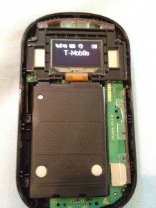
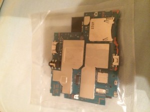
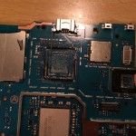
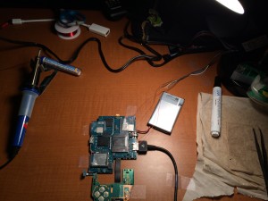
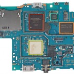
It does not have to be fully working. On eBay, people are selling Vita logic boards with broken connectors for around this price (after shipping).

  • Heat Gun – $21

    Heat Gun
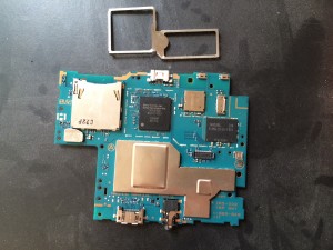
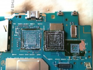
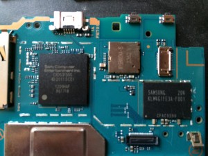
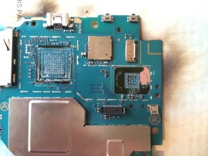
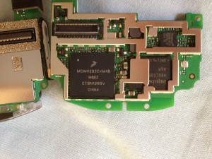
A heat gun is needed to remove the surface mounted NAND and SoC. It’s also why reattaching it almost impossible because the hot air will blow the components around.

  • Soldering Tools – $20

    Soldering Tools
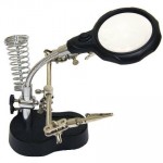
I do have basic soldering tools, but throughout the project, there will be tasks that require more precision, so I would need a magnifying soldering station (cheapest is $15 on Amazon), soldering flux (about $5 on Amazon), and some small tools.

  • Digital Multimeter – $10

    MultimeterA cheap one will do. I only need it for continuity testing and reading resistor values.

  • Saleae Logic Analyzer (clone) – $10

    Saleae Clone
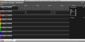
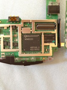
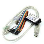
Although a real Saleae logic is $150 (for 8 ports) or $300 (for 16 ports), there’s some cheap clones on eBay going for about $10. This would allow me to find signals coming out of a running Vita and, for example, verify that the test points found are indeed data driven.

Goal 2: Dumping the NAND and Testing ($250)

After getting all the tools and finding the traces, the first thing to do is to dump the NAND from a working console. This should be easy once the trace is found since the NAND is eMMC (can be dumped using an SD card reader). Next, I want to explore the signals coming into and out of the Vita (USB, multi-connector, mystery port, memory card, game card). Then depending on what I find, I’ll go from there.

  • PlayStation Vita Console – $100-150

    Vita
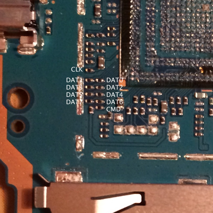
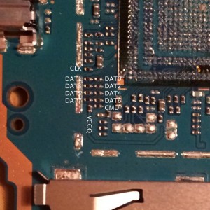
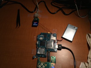
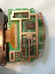
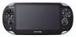
This would be the working console that I will test with. First, I will dump the NAND with the test points found. Then I will try to analyze the game card and memory card traffic using the logic analyzer. Although the console should be working, to save money, I may get one with a broken screen, which goes for around $100 on eBay or a used unit for $150 on CowBoom. If you own a broken Vita, and want to donate it instead of money, please contact me.

  • PlayStation VitaTV Console – $120

    VitaTV
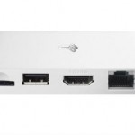
First a NAND dump of the VitaTV would be interesting to see if there’s any differences (assuming it’s not encrypted). Also, I would like to see how the HDMI port is connected (4gamer suspect that HDMI out comes directly from the SoC) and see if I can get a regular Vita to output HDMI (most likely not possible without software and hardware modifications). I also want to do some software tests on the VitaTV as the introduction of USB host may also introduce new bugs into the system (remember how the PS3 was hacked). It seems to be about $120 after shipping from Nippon-Yasan. If you want to donate a VitaTV directly instead of money, please contact me.

  • PlayStation Vita Cradle – $15

    vita_cradle
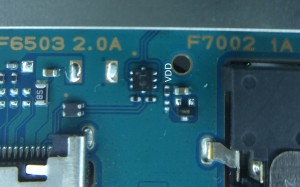
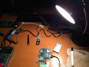
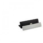
The Vita cradle is a good pin-out interface for the Vita multi-connector. By soldering to the cradle, it would minimize the risk of damage to the Vita directly. Exploring the multi-connector is a good way to start since there are 16 pins and only a few of them are figured out.

  • (Optional) PlayStation Vita PCH-2000 – $220

    vita_pch-2000
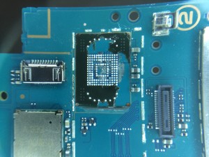
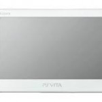
This is purely optional and only if someone generous would like to donate the console to me directly. There’s not much I want to do here except dump the NAND and trace the microUSB signals.

Unlimited Backgrounding on iOS

$
0
0

Since iOS4, developers have the ability to perform background tasks with some limitations. Background tasks must fit one of the five different categories for background supported apps. Music and streaming apps can be backgrounded as long as they play music. Newsstand apps can wake once a day to download updates. Location aware apps can wake up once in a while to update their position. VOIP apps can have one socket (I found out the hard way that the one socket does not include listener sockets) connected in the background. General apps can request up to 10 minutes to finish some task. While this is enough for most backgrounding purposes, sometimes we need backgrounding for more advanced tasks. Specifically, I wanted to write a HTTP proxy server that runs on the device (in the future, this proxy server will work as an ad-blocking proxy) in the background. I will show you the steps of making this work. Please note that Apple will certainly reject any app that abuses their backgrounding policy so doing so would only be useful for personal and enterprise uses.

So how are we going to abuse the iOS background policy? We are going to declare our app as a background music player but not play any music. Sounds simple right? Well, in hindsight it is, but there’s some subtle tricks I had to discover to get it all working. Let’s go through this step by step…

First make sure your app has, in “Capabilities”, Background Modes turned on and “Audio and AirPlay” enabled. Also make sure you’re linking with “AVFoundation.framework.”

In our demo app, we will have one button that says “Enable Background” that, when tapped, will keep our app running even if the user switches apps. We also have a NSThread will will keep logging to show that it is running even in the background.

First create your silent music file. I had success with a one-second MP3 file of silence. The audio file does not have to be silent, but why scare the user with a random audio file? Add this to the “Supporting Files” category.

Add a property to the View Controller that will hold the silent audio player.

@property (nonatomic, strong) AVPlayer *player;

Now, you should set up the audio session. I chose to do this in viewDidLoad of my view controller of the single view in the demo app.

NSError *sessionError = nil;
[[AVAudioSession sharedInstance] setCategory:AVAudioSessionCategoryPlayback withOptions:AVAudioSessionCategoryOptionMixWithOthers error:&sessionError];

The category AVAudioSessionCategoryPlayback is one of the few categories that allow for backgrounding. The option AVAudioSessionCategoryOptionMixWithOthers will make sure your silent audio won’t stop any currently playing background audio and also make sure that when the user plays music in the future, it won’t kick off your background task. A good developer will also check the return values and sessionError, but I’m not a good developer.

AVPlayerItem *item = [AVPlayerItem playerItemWithURL:[[NSBundle mainBundle] URLForResource:@”silence” withExtension:@”mp3″]];
[self setPlayer:[[AVPlayer alloc] initWithPlayerItem:item]];

Now create the actual player item for your silent audio file. If you are embedding your audio file a different way, feel free to adapt this to do so. No trickery here.

[[self player] setActionAtItemEnd:AVPlayerActionAtItemEndNone];

Here’s the trick; this makes sure that the audio player is kept active after playing your sound file. The alternative is to keep looping a silent track, but why waste more CPU cycles (and battery)?

Now, whenever you wish to keep the app in the background, just call

[[self player] play];

And your app will keep working even after the user switches the app. In my case, the HTTP proxy server was still working after I left the iPad in sleep mode overnight (with the charger connected of course).

Here is the sample code: Limitless Background (52)

Removing the CPU and NAND from PSVita

$
0
0

Thanks again to everyone who helped fund this project! This is the first part of the long journey into hardware land. I bought a non-working Vita logic board from eBay, which arrived yesterday, packaged like a freeze-dried snack.

As delicious as it looks.

As delicious as it looks.

In order to locate the trace from the eMMC (aka the NAND), my plan was to take a broken logic board and remove the eMMC chip and use the exposed pads and trace it to a test point or something. Then take another Vita logic board (this time with the eMMC still attached) and solder wires to the test point and dump it with an SD card reader or something (as eMMC uses the same interface as SD cards). This is a complicated plan, but it’s necessary because I am not professional enough to be able to remount the eMMC (which is a tiny fine-ball-grid-array (FBGA) chip) once the trace is found.

First, you have to remove the EFI shields. The actual shields are fairly easy to remove; they are clicked into the base, and all it takes is a little pry from all sides (careful not to destroy any components near-by). However, the hard part is getting the surface mounted base off. Removing the base is recommend because it allows easier access to the eMMC, and if the test point happens to be close to the chip, it would be impossible to solder with the base in place.

Before starting, make sure the board is completely stable (since a lot of prying will be performed). I chose to tape the board to a unwanted book (which had burnt marks at the end; don’t know if the heat gun reaches the autoignition temperature, so in hindsight that was not a good idea) but having clamps would be a better solution. When using the heat gun, keep it fairly close to the board (about an inch off) and on the low setting.

To remove the base, heat up the board with a heat gun (to prevent too much expansion in one area) and direct the heat at the edge of the base near the eMMC. Wave the heat gun slowly across the entire edge while using the other hand to try to pry the base off with a pointy-metal-apparatus (scientific term; perhaps a flat head screwdriver will do). As the base peels off, move the heat gun to the next position where the base is still attached and repeat until the entire base is off. Be careful not to move the board too much or accidentally touch any of the tiny components all around because even though the board will not be used anymore, you don’t want to destroy a potential path from the eMMC.

Freed from its Faraday cage

Freed from its Faraday cage

To remove the actual eMMC chip, keep the heat gun directed at the chip for a while, then use your pointy device to try to pry it off. Use a bit of force but not extreme force and be slow with the prying. This is because even though the solder below melts fairly quickly, the chip is held in place with some kind of glue (most likely so during the manufacturing process, when surface mounting the other side of the board, the chip doesn’t fall off). If you pry too hard or too quickly, you may rip some unmelted solder off or (as in my case), actually rip off the solder mask below the glue.

Notice the burnt paper underneath. Don't try this at home.

Notice the burnt paper underneath. Don’t try this at home.

You can repeat the process for the SoC if you wish, although more care should be applied here since there are so many tiny components near the chip.

I was a bit better this time and didn't strip any solder mask.

I was a bit better this time and didn’t strip any solder mask.

Congratulations! You have destroyed the Vita beyond the possibility of recovery.

Before the destruction of a great piece of engineering

Before the destruction of a great piece of engineering

Vita with those useless chips removed

Vita with those useless chips removed

In hindsight, I should have used a hot air rework gun instead of a paint-stripping heat gun, as someone in the comments suggested last time. Then, maybe it wouldn’t look so bad. But luckily, it seems that all of the components are still attached to the board, so tracing wasn’t so hard. The bad news is that after tracing, it seems that the only exposed connection I could find from the data pins of the eMMC to the SoC was in the pile of tiny resistors next to the SoC. Tune in next time to see more amateur mistakes and destruction.


PS Vita NAND Pinout

$
0
0

Vita NAND Pinout

As promised, here’s the pinout for the Vita’s eMMC (NAND). Don’t be fooled by the picture; the size of the resistors are TINY. Plus, if you noticed, half the traces are almost hugging the shield base (which is pretty hard to remove without disturbing the resistors). I hope I can find a better way to dump the eMMC than soldering to these points. It’s doubtful that they are exposed elsewhere as I’ve checked every unfilled pad on both sides of the board. Wish me luck…

To get an idea of where these resistors are located, check the iFixit picture for reference (black box is where they are).

To get an idea of where these resistors are located, check the iFixit picture for reference (black box is where they are).

Comparsion

To get an idea of the size of the resistors, I’ve placed a 0.7mm pencil lead next to them.


Random observations on Vita logic board

$
0
0

While I’m waiting for more tools to arrive, here’s some things I’ve found while playing around with the continuity test on a multimeter. There is no stunning discovery here, just bits and pieces of thoughts that may not be completely accurate.

On Video Out

The unfilled pads next to the eMMC has something to do with video. The direction of the trace goes from the SoC to the video connector. A continuity test shows that all the pads comes from the SoC and leads to some point on the video connector. Could they be pads used for testing video in factory? Looking at the VitaTV teardown from 4gamer.net shows that traces in a similar location coming out of the SoC goes through similar looking components and then into the Op-Amp and to the HDMI connector. This is a stretch, but could these traces output HDMI if connected properly? As a side note, I could not find any direct connection between anything on the video connector to either the mystery port or the multi-connector. If Sony were to ever produce a video-out cable, there needs to be a software update as there doesn’t seem to be hardware support.

On the Mystery Port and USB

The first two pins on the mystery port appear to be ground (or Vdd and Vss). The last pin could be a power source. Pins 3 and 4 goes through a component and directly into the SoC. What’s interesting is that the D+/D- USB line from the multi-connector on the bottom goes through a similar looking component and that they are very close to the pins that handle the mystery port. Looking at 4gamer.net’s VitaTV teardown again, we see that the USB input port has two lines that go through very similar paths (the various components that it goes through) as the Vita’s USB output, but the position of the traces going into the SoC on the VitaTV is the same position of the trace on the Vita coming from the mystery port. Could the mystery port be a common USB host/USB OTG port with a custom plug?

On the Mystery Chip

Also 4gamer.net speculates the SCEI chip on the top of the board has something to do with USB, but I think that’s not true because USB lines go directly into the SoC. Which means that we still don’t know what the SCEI chip does (it is the only chip on the board that has yet been identified by any source). My completely baseless hypothesis is that it’s syscon because it would be reasonable to assume that the syscon is outside of the SoC since it would decide when to power own the SoC.

On the eMMC

This may be public knowledge but the Vita’s eMMC NAND is 4GB (same as VitaTV and Vita Slim). The new Vitas do not have any additional storage chips. This also means that the 1GB internal storage on the new Vitas is just another partition or something on that NAND (no hardware changes).

Updates on the Vita Hardware Hacking project

$
0
0

After a week of trying to dump the eMMC (spoilers: didn’t happen yet), I’ve decided to post this update about things I’ve tried to do (and how I tried to do it) and where the money is going to.

Supplies

I had two Vita logic boards. The first one, which I removed the SoC and eMMC to find the trace points (shown previously), came from eBay. The second board came from a Vita with a broken screen generously donated by @Amxomi. I also bought a professional rework station, the X-Tronic 4040 which was paid partially by your donations (I returned the heat gun) and partially thanks to wololo. For wiring, the thinnest wire I could find is enamel-coated magnet wire. For soldering the wires, I got 60/40 Rosin solder and a Rosin flux pen.

Attempt One

The first thing I did was remove the EMI shield base blocking the test point resistors. With the reflow station’s hot air gun, it was much easier than the heat gun I used last time. Next I warmed up my soldering skills by hooking wires up to a microSD to SD card adapter. My plan was to attach the wires to the test point and plug the SD card into a SD card reader. To expose the copper in the enamel-coated wire, I melted a blob of solder and kept it on the tip of the iron at 400C. Then I dipped the tip of the wire into the liquid solder, which both coats the tip of the wire with solder and also removes the coating. It’s a neat trick that I used all the time throughout the rest of the ordeal.

Then I brushed the pins of the microSD adapter with flux and quickly melted a small blob of solder on each pin. Then with a pair of tweezers, I held each wire next to the pin, and as soon as it is heated, the small bit of solder on the wire joins with the blob on the pin and they connect.

It gets much harder connecting the other end. There is very little exposed solder on the tiny resistors, and it is very hard to add more because you might accidentally short circuit two adjacent pads. I made sure there is a bit of solder on the end of the wire using the trick. Then I held the end of the wire steady with the tweezer while tapping it with the iron. It takes many tries for it to stick on, and many times when trying to attach the neighboring pads, the heat from the iron loosens the other wires. In addition, accidentally bumping into the wire causes enough stress to rip the solder off the resistor (because there is so little solder), so I just taped everything to a piece of cardboard. I also can’t test if my joints are correct and not shorted with any other joints because of how small and close everything is.

After a couple of hours, the wires are soldered to the points but there are a couple of problems. First, as mentioned, I couldn’t test the correctness of my connections. Second, I don’t know if in the process of soldering to the tiny resistors, I damaged any resistors and if so, would it still work. Third, I never found a test point for Vdd because for some reason, Vdd shorts to Vss/Ground on my first board. As expected, after plugging the microSD adapter into a reader into the computer, nothing shows up. Because there could be so many problems, I removed all the wires and started over.

Attempt Two

First, I located a test point for Vddf (Vdd is power to the eMMC controller while Vddf is power to the actual NAND chip). My hypothesis is that the same power source that powers Vddf also powers Vdd (although the Samsung documents recommends against this). This point is on top of the tiny resistor to the left of the audio jack.

Next, I decided to remove all of the 150ohm resistors on the test points in order to get more solder surface area. Looking at the eMMC testpoints picture from last time, it’s important to note that the pad on the left of each resistor is the one coming from the eMMC while the pad on the right of each resistor is the one going to the SoC. The resistors themselves may be for current limiting or noise removal. Removing them is as simple as pointing at it with the hot air gun set to 380C for half a minute and then using tweezers to to remove them.

I also found it easier to solder wires directly to the SD card reader instead of to an microSD to SD card adapter. I first verified that the card reader still works and that my wires are not too long by soldering the other end of the wire directly to an old 128MB SD card. After verifying, I removed the wires from the SD card and attached them to the now exposed test points.

Unfortunately, it still didn’t work. The computer sees the SD card reader but believes no card is inserted. Again, there could be any number of problems including (still) bad soldering, Vdd not receiving power, or even read protection in the eMMC.

Attempt Three

Next I made another attempt to find Vdd. The problem is that my multimeter shows a short from Vdd to Vss. This means that Vdd is somehow shorted to ground either because I broke something with all the heat and bad soldering or because that is by design (which I don’t think is true because all documents I read say that you need to power Vdd for the eMMC controller to work). I thought maybe I can experiment by sending test voltages through various locations on the first logic board (the one with the chips removed) and see if I get a voltage drop in the Vdd pad. I used an old broken MP3 player as my voltage source (since it was just laying around and I didn’t want to buy a power supply, rip open any working cable/device, or solder to a battery). I attached the positive end to a pointed screwdriver and the negative end to the Vita’s ground. Then I attached one probe of my voltmeter to the same ground. Then with the screwdriver in one hand and the voltmeter probe in the other hand, I tried to send voltage through every location on the board. Unfortunately, the only response was sparks on capacitors here and there but no response in Vdd.

Back to the second Vita, I tried to attach the battery and charger and turned it on. At first, I got excited and saw a voltage drop on the eMMC’s decoupling capacitor (meaning there’s power going to the eMMC). However, after going back and reattaching the wires, I could no longer reproduce the result. In addition, the power light no longer responds to the power switch. I believe that I shorted something and the first time I powered it on, it destroyed some component; so the next time I attempted to power it on, it fails before even attempting to power the eMMC.

Regardless, I tried to reattach all the wires with better soldering on the assumption that my only problem is still the bad soldering (likely not true). Being the fourth or fifth time doing this, I am getting better at soldering these extremely tiny points. My trick was to first align the wire to the board and then using the tweezer, make a 90 degree bend on the end of the wire. This makes the end of the wire the same length as the original resistors. Then I quickly dip the end in solder, flux the board, and attach the wire to two pads instead of one. This makes a stronger connection. Even though I did a much better job and soldering the test points, I still could not get anything to show up on my computer.

Attempt Four

Now that I have experience in soldering tiny points, I made an attempt at soldering directly to the eMMC removed from the first Vita. However, after a quick test (nothing shows up on the computer), I didn’t look any farther because I believe that the eMMC must be part of a circuit of capacitors and resistors in order for it to work (and not break the chip). All documents I’ve read supports this.

I also made yet another attempt at resoldering to the board again and still no luck. At this point, I believe that either I still am not powering Vdd correctly, or I broke the eMMC at some point. I also suspect that perhaps my SD card reader does not support the Samsung eMMC or that it is not being initialized correctly.

What’s Next

I still haven’t given up. I will continue to try resoldering the points. I still want to find a way to surely power Vdd; I bought another Vita from eBay because I believe the second Vita is now broken. I also ordered a eMMC socket with the last of the usable donations, but it will take at least a month to arrive from China. There’s also the possibility that the eMMC does something unsupported by my SD card to USB adapter and I want to do some raw signal interaction with an Arduino. If you want live updates of progress as I’m working, join #vitadev on EFnet.

Professional soldering and reflow station fresh out of the box. microSD to SD adapter torn apart and wires soldered in Shield removed on new board. Much easier this time with a reflow station. Another angle. Old logic board. The trace points with the resistors removed. Old board. Coupling capacitors next to the eMMC removed. Attempt 1: Wires soldered directly to resistors and to an adapter. Look at the horrible soldering job Attempt 2: Resistors removed. Vddf found and soldered to Vdd from SD reader. Wired directly to a USB SD card reader Contraption built to send test voltages to board. Attempt 3: Refluxed pads and tried again Better soldering job this time Attempt 4: Tried hooking wires up directly to eMMC and SD adapter Attempt 4: Also tried resoldering pads one more time Zoomed out

PS Vita NAND Pinout (Updated)

$
0
0

Since the last post on the eMMC pinout, I found the other two important test points. First is VCCQ, which is the power to the eMMC controller. It needs to be pulled at 1.8V. The other point is VCC, which is the power to the actual NAND flash. It needs to be pulled at 3.3V.

Found on the bottom of the board, above the SoC

Found on the bottom of the board, above the SoC

Found on the bottom of the board, near the multi-connector

Found on the bottom of the board, near the multi-connector

For reference, the pad of the removed eMMC on the second Vita

For reference, the pad of the removed eMMC on the second Vita


Dumping the Vita NAND

$
0
0

When we last left off, I had spent an excess of 100 hours (I’m not exaggerating since that entire time I was working, I listened to This American Life and went through over a hundred one-hour episodes) soldering and tinkering with the Vita logic board to try to dump the eMMC. I said I was going to buy a eMMC socket from taobao (the socket would have let me clamp a eMMC chip down while pins stick out, allowing the pressure to create a connection) however, I found out that all the sellers of the eMMC socket from taobao don’t ship to the USA and American retailers sell the sockets for $300 (cheapest I could find). So I took another approach.

Packet Sniffing

My first hypothesis on why it is not working is that there’s some special initialization command that the eMMC requires. For example, CMD42 of the MMC protocol allows password protection on the chip. Another possibility was that the chip resets into boot mode, which the SD card reader doesn’t understand. To clear any doubts, I connected CLK, CMD, and DAT0 to my Saleae Logic clone I got from eBay.

Vita eMMC points connected to logic analyzer.

Vita eMMC points connected to logic analyzer.

As you can see from the setup, I had the right controller board attached so I can get a power indicator light (not required, but useful). I also took the power button out of the case and attached it directly. The battery must be attached for the Vita to turn on. Everything is Scotch-taped to the table so it won’t move around. Once all that is done, I captured the Vita’s eMMC traffic on startup.

First command sent to eMMC on startup

First command sent to eMMC on startup

After reading the 200 paged specifications on eMMC, I understood the protocol and knew what I was looking at. The very first command sent to the Vita is CMD0 with argument 0×00000000 (GO_IDLE_STATE). This is significant for two reasons. First, we know that the Vita does NOT use the eMMC’s boot features. The Vita does not have its first stage bootloader on the eMMC, and boots either from (most likely) an on-chip ROM or (much less likely) some other chip (that mystery chip on the other side maybe?). Second, it means that there’s no trickery; the eMMC is placed directly into Idle mode, which is what SD cards go into when they are inserted into a computer. This also means that the first data read from the eMMC is in the user partition (not boot partition), so the second or third stage loader must be in the user partition of the eMMC. For the unfamiliar, the user partition is the “normal” data that you can see at any point while the boot partition is a special partition only exposed in boot mode (and AFAIK, not supported by any USB SD card reader). Because I don’t see the boot partition used, I never bothered to try to dump it.

Dumping

I tried a dozen times last week on two separate Vita logic boards trying to dump the NAND with no luck. Now that I’m on my third (and final) Vita, I decided to try something different. First, I did not remove the resistors sitting between the SoC and eMMC this time. This is because I wanted to capture the traffic (see above) and also because I am much better at soldering now and the tiny points doesn’t scare me anymore. Second, because of my better understanding of the MMC protocol (from the 200 page manual I read), I no longer attempted to solder DAT1-DAT3 because that takes more time and gives more chance of error due to bad connections. I only connected CLK, CMD, and DAT0. I know that on startup, the eMMC is placed automatically into 1-bit read mode and must be switched to 4-bit (DAT0-DAT3) or 8-bit (DAT0-DAT7) read mode after initialization. My hypothesis is that there must be an SD card reader that followed the specification’s recommendation and dynamically choose the bus width based on how many wires can be read correctly (I also guessed that most readers don’t do this because SD cards always have four data pins). To test this, I took a working SD card, and insulated the pins for DAT1-DAT3 with tape. I had three SD card readers and the third one worked! I know that that reader can operate in 1-bit mode, so I took it apart and connected it to the Vita (CLK, CMD, DAT0, and ground).

As you can see, more tape was used to secure the reader.

As you can see, more tape was used to secure the reader.

I plugged it into the computer and… nothing. I also see that the LED read indicator on the reader was not on and a multimeter shows that the reader was not outputting any power either. That’s weird. I then put a working SD card in and the LED light turned on. I had an idea. I took the SD card and insulated every pin except Vdd and Vss/GND (taped over every pin) and inserted the SD card into the reader. The LED light came on. I guess there’s an internal switch that gets turned on when it detects a card is inserted because it tries to draw power (I’m not hooking up Vdd/Vss to the Vita because that’s more wires and I needed a 1.8V source for the controller and it’s just a lot of mess; I’m using the Vita’s own voltage source to power the eMMC). I then turned on the Vita, and from the flashing LED read light, I knew it was successful.

LED is on and eMMC is being read

LED is on and eMMC is being read

Analyzing the NAND

Here’s what OSX has to say about the eMMC:

Product ID: 0×4082
Vendor ID: 0x1e3d (Chipsbrand Technologies (HK) Co., Limited)
Version: 1.00
Serial Number: 013244704081
Speed: Up to 480 Mb/sec
Manufacturer: ChipsBnk
Location ID: 0x1d110000 / 6
Current Available (mA): 500
Current Required (mA): 100
Capacity: 3.78 GB (3,779,067,904 bytes)
Removable Media: Yes
Detachable Drive: Yes
BSD Name: disk2
Partition Map Type: Unknown
S.M.A.R.T. status: Not Supported

I used good-old “dd” to copy the entire /dev/rdisk2 to a file. It took around one and a half hours to read (1-bit mode is very slow) the entire eMMC. I opened it up in a hex editor and as expected the NAND is completely encrypted. To verify, I ran a histogram on the dump and got the following result: 78.683% byte 0xFF and almost exactly 00.084% for every other byte. 0xFF blocks indicate free space and such an even distribution of all the other bytes means that the file system is completely encrypted. For good measure, I also ran “strings” on it and could not find any readable text. If we assume that there’s a 78.600% free space on the NAND (given 0xFF indicates free space and we have an even distribution of encrypted bytes in non-free space), that means that 808.70MB of the NAND is used. That’s a pretty hefty operating system in comparison to PSP’s 21MB flash0.

What’s Next

It wasn’t a surprise that the eMMC is completely encrypted. That’s what everyone suspected for a while. What would have been surprising is if it WASN’T encrypted, and that tiny hope was what fueled this project. We now know for a fact that modifying the NAND is not a viable way to hack the device, and it’s always good to know something for sure. For me, I learned a great deal about hardware and soldering and interfaces, so on my free time, I’ll be looking into other things like the video output, the mystery connector, the memory card, and the game cards. I’ve also sent the SoC and the two eMMC chips I removed to someone for decapping, so we’ll see how that goes once the process is done. Meanwhile, I’ll also work more with software and try some ideas I picked up from the WiiU 30C3 talk. Thanks again to everyone who contributed and helped fund this project!

Accounting

In the sprit of openness, here’s all the money I’ve received and spent in the duration of this hardware hacking project:

Collected: $110 WePay, $327.87 PayPal, and 0.1BTC

Assets

Logic Analyzer: $7.85
Broken Vita logic board: $15.95
VitaTV x 2 (another for a respected hacker): $211.82
Rework station: $80
Broken 3G Vita: $31
Shipping for Chips to be decapped: $1.86

Total: $348.48 (I estimated/asked for $380)

I said I will donate the remaining money to EFF. I exchanged the 0.1BTC to USD and am waiting for mtgox to verify my account so I can withdraw it. $70 of donations will not be given to the EFF by the request of the donor(s). I donated $25 to the EFF on January 10, 2014, 9:52 pm and will donate the 0.1BTC when mtgox verifies my account (this was before I knew that EFF takes BTC directly).

Viewing all 77 articles
Browse latest View live